|
| |
| THE FLAVEL COMBINATION STAINLESS STEEL SINK UNIT AND HOTPLATE |
| |
| HOW TO USE THIS APPLIANCE ECONOMICALLY |
| |
| HOTPLATE |
Both burners can be used for fast boiling or simmering, and are controlled by safety taps of the self-locking type.
To turn on gas, push in fan and turn in an anti-clockwise direction.
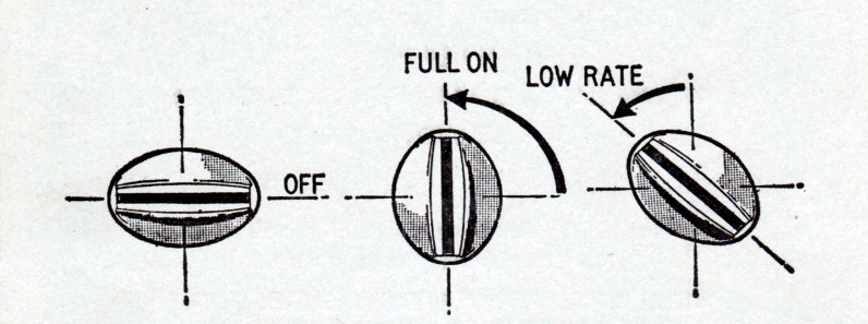
The FULL ON rate is obtained when the tap is turned through 90° and a stop indicates when this has been reached. For the LOW position push in fan and turn a further 45°. However, if desired, the output of the burners can be set to any position other than the fixed LOW rate, by setting the control knob between LOW rate and FULL ON, or between FULL ON and OFF.
It is wasteful to use a saucepan less than 4 inches in diameter, as the flames will spread beyond the base of the saucepan. Make sure that the base of every kettle, saucepan or frying-pan is smooth. Any roughness may damage the chromium plating of the pan support. |
 |
| GRILL |
| Whilst the grill is heating up, place the empty grill pan under the lighted burner to protect the surface within the cabinet. When the grill is hot, place the loaded pan in the cooking position. |
| CLEANING |
After use, whilst the hotplate is still just warm, wash with warm soapy water. If this is done regularly your hotplate will remain in good condition. Spillage should be wiped off as soon as possible.
Do not use soda, abrasive or caustic cleaning agents on any of the surfaces.
|
| ADJUSTMENT |
| Your supplier will leave your unit correctly fitted and adjusted, and should be informed immediately if any subsequent service is required. No one else should be allowed to interfere with the unit. |
| |
|
 |
The unit is supplied in two packs.
Pack 1 - Stainless steel sink - Size A 1050 x 400. B 1200 x 400, C 1200 x 500 as Ordered. (Guard Rail supplied with sizes B and C.)
Pack 2 - Hotplate unit assembly together with |
- Pan Support
- Grill Pan and Grid
- Facia Panel
- Facia Panel fixing screws and washers
- Control Knobs and Clips
- Hotplate fixing screws and washers
|
 |
General information and dimensions required for assembly of unit into cabinet ( Figs. 1 and 1a).
It is important that measurements shown in Figs. I and la are strictly adhered to. Walls and base of the compartment to be lined with a non-combustible material and suitably insulated. |
| |
 |
| HOTPLATE ASSEMBLY PROCEDURE (Fig. 2) |
First remove burner head, collar and seal (2 off) by undoing screw on underside of burner unit. Ensure that the two sealing pads on the top side of the burner unit and the two on the underside of the burner seals (which have been fixed by the manufacturer) are not damaged and are still in their correct position.
Next fix burner unit to stainless steel sink unit with the two screws and washers provided. It is important that the burner spigots are centralised into the sink unit.
Stand sink unit on back edge and place the seal on to the burner collar, position on spigot and locate into cut out on sink unit. Hold in position and place burner head on to collar and fix with screws and washers and tighten firmly,
|
| NOTE: Care should be taken to ensure that seal is not damaged during this operation. |
Repeat procedure for second burner.
Fit pan supports by pressing the extended legs of the wire frame into the two holes provided in the top face of the sink unit. The pan support will then automatically be secured by spring clips under the unit.
Fit facia panel with screws and washers provided.
Fit control knobs by pushing on to tap spindles. Line flats on spindle with spring clips.
The unit is now read/ for installation.
When installing sizes 1200 x 400 and 1200 x 500 with centre bowl, this should be assembled as shown on Fig. la.
|
INSTALLATION |
| GAS CONNECTION |
This is situated on the left-hand side of the hotplate and the fitting is J" BSP male thread. It is recommended that unit be fixed using Copper Tubing.
|
| LINE PRESSURE |
The hotplate is designed to work at a line pressure of 11" w.g. for Butane and 14" w.g. Propane. It is important that the regulator should be set to this pressure when it is installed and checked occasionally afterwards. Excessive pressure must not be permitted.
|
| HOTPLATE TAPS |
The taps are self-locking in the OFF position. To operate push in fan and turn in an anci-clockwise direction. The FULL ON rate is obtained when the tap is turned through 90° and a stop indicates when this has been reached. For the LOW rate position, push in fan and turn a further 45° (see illustration below). However, if desired, the output of the burners can be set to any position other than the fixed LOW rate, by setting the control knob between LOW rate and FULL ON, or between FULL ON and OFF.
|
| NOTE: Advise customer on the correct use of the hotplate and ensure they have been handed the copy of the User's Instruction. |
|
| AERATION |
Both hotplate burners and the grill burner should show blue flames without white tips. The aeration can be adjusted by means of the control screw fitted on each burner.
|
| DRAUGHT |
The hotplate must be installed and operated according to the maker's instructions, and no alterations should be made to the injectors, burners or the line pressure, except by the supplier's representative. If any smell of unburned gas is observed, the supply should be immediately turned off at the cylinder, all windows opened and time allowed for the gas to disperse before an investigation is made. |
| INJECTOR SIZES |
| |
|
HEAT INPUT |
GAS RATE |
| BURNER |
SIZE |
PROPANE 14" W.G.
|
CU. FT./HR. |
| |
|
BUTANE 11" W.G. |
BUTANE |
PROPANE |
| Boiling (Two) |
60 |
6,000 |
1.85 |
2.40 |
| Grill |
90 |
9,000 |
2.81 |
3.60 |
| On no account should the injectors be interfered with except to clean with a non-abrasive probe if necassary. |
|
Download in PDF Format |